


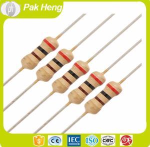
1/8W 1/4W 1/2W 1W 2W 3W 5WColor Coding Formula Thin Layer 2% 5% 10% Carbon Film Resistors
-
Payment


-
Origin
China Mainland
-
Minimum Order
1
-
Packing
Pieces
- Contact Now Start Order
- Description
Product Detail
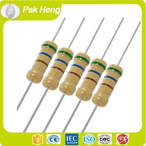
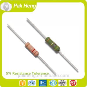
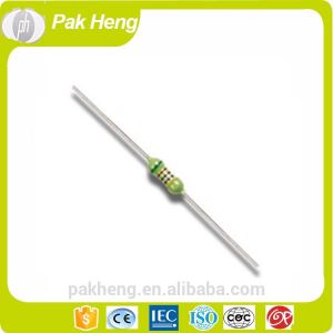
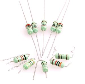
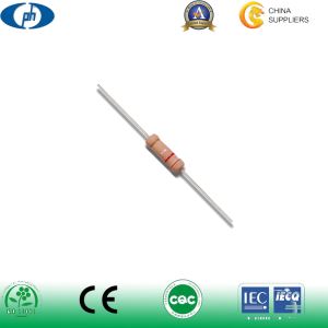
Carbon film resistors use a thin layer of carbon on top of an insulating rod which is cut to form a narrow, long resistive path.By controlling the length of the path and its width, the resistance can be precisely controlled with tolerances as tight as 1%. Overall, the capabilities of a carbon film resistor are better than a carbon composition resistor, with power ratings up to 5 watts and better stability. However, their frequency response is much worse due to the inductance and capacitance caused by the resistive path cut in to the film
.
Features:
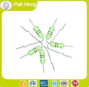
1?Stable performance, extensive resistance, small size,high operating temperature and high ultimate voltage.
2? Highly adaptive pulse load, good high frequency performance.
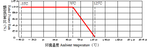
3? Operating ambient temperature: -55?~+125?.
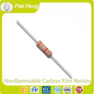
4? The resistor’s normal size coats yellow and the mini size coats brown.
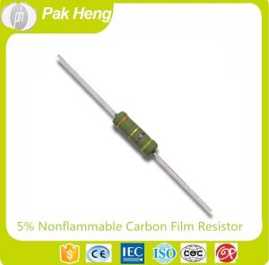
5? Resistance tolerance:±2%?±5%?±10%.
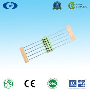
Construction Drawing:
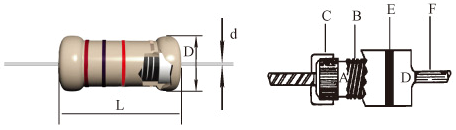 A?High heat exchanged Ceramic core.
B?High stability Electric conduction film.
C? Iron Cap.
D?Epoxy resin coating.
E?Color Ring.
F?Tinned copper lead wire or CP lead wire.
Rated Power Derating Curve:
![]()
![]()
Performance Test:
Test Item | Test Condition | Performance |
Temperature coefficient | Test the resistance value at normal temperature and normal temperature added 100?,calculate per? resistance value change rate . | ±1000ppm/? |
Short time overload | 2.5 × rated voltage or Max.overload voltage (get the lower) for 5 seconds. | ?R=±(1%R0+0.05O) |
Pulse overload | At 4 × rated voltage or Max. pulse overload voltage (get the lower) cycle 10000±200 times(1 second on, 25 seconds off ). | ?R=±(2%R0+0.05O) |
Resistance to soldering heat | Immerge into 350±10? tin stove for 2~3 seconds. | ?R=±(1%R0+0.05O) |
Solderability | Immerge into 245±3? tin stove for 2~3 seconds. | The area of soldering is over 95% |
Temperature cycling | At -55? for 30 min, then at +25? for 10~15 min, then at +125? for 30 min, then at +25? for 10~15 min, total 5 cycles. | ?R=±(1%R0+0.05O) |
Load life in humidity | Overload rated voltage or Max.working voltage (get the lower) for 1000 hours (1.5 hours on and half-hour off ) at the 40±2? and 90~95% relative humidity. | ?R=±(5%R0+0.05O) |
Load life in heat | Overload rated voltage or Max.working voltage (get the lower ) for 1000 hours (1.5 hours on and half-hour off) at the 70±2?. | ?R=±(5%R0+0.05O) |
Dimentions and Voltage Performance
?? Part No. | ?? Power | ???? Resistance range | ??Dimensions(mm) | ??????Max.working voltage | ??????Max.overload voltage | ??????Max.Pulse voltage | ??????Max.insulation voltage | ||
L±1 | D±0.5 | d±0.05 | |||||||
CCR016 CFR016 | 1/8W 1/6W | 0R~22M | 3.5 | 1.7 | 0.41 | 200V | 400V | 500V | 300V |
CCR14S CFR14S | 1/4WS | 0R~22M | 3.5 | 1.7 | 0.41 | 200V | 400V | 500V | 300V |
CCR014 CFR014 | 1/4W | 0R~22M | 6.0 | 2.3 | 0.45 | 250V | 500V | 750V | 500V |
0.52 | |||||||||
CCR12S CFR12S | 1/2WS | 0R~22M | 6.0 | 2.3 | 0.45 | 250V | 500V | 750V | 500V |
0.52 | |||||||||
CFR012 | 1/2W | 0R1~22M | 9.0 | 3.2 | 0.58 | 350V | 700V | 1000V | 700V |
CFR01S | 1WS | 0R1~22M | 9.0 | 3.2 | 0.58 | 350V | 700V | 1000V | 700V |
CFR01B | 1W | 0R1~22M | 11.0 | 4.5 | 0.75 | 500V | 1000V | 1000V | 1000V |
CFR02S | 2WS | 0R1~22M | 11.0 | 4.5 | 0.75 | 500V | 1000V | 1000V | 1000V |
CFR02B | 2W | 0R1~22M | 15.0 | 5.0 | 0.75 | 500V | 1000V | 1000V | 1000V |
CFR03S | 3WS | 0R1~22M | 15.0 | 5.0 | 0.75 | 500V | 1000V | 1000V | 1000V |
CFR03B | 3W | 0R1~22M | 24.0 | 8.0 | 0.75 | 700V | 1200V | 1200V | 1000V |
CFR05S | 5WS | 0R1~22M | 24.0 | 8.0 | 0.75 | 700V | 1200V | 1200V | 1000V |
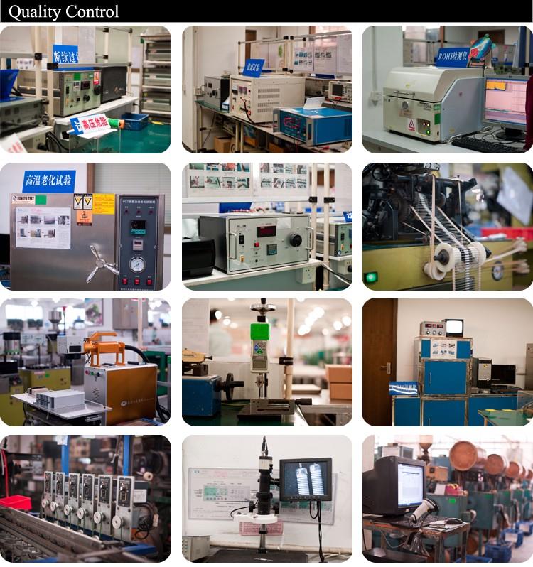
Due to our outstanding quality and excellent services,we won a good reputation in the resistors industry field.We have streng technical strength,
advanced preduction and test equipments.All the main raw materials are purchased from Germany,Japan and Taiwan.in the preduction precess,
we strictly carry Out the IEC standards,can according customers special requirements to carry out the Japan JIS or Amerlca MIL standards.We can
produce all series resistors,such as Chip Resistors,Chip Array Resistors, Array Resistors,Carbon Film Resistors,Metal Film Resistors,Metal Oxide
Film Resistors,Fuse Resistors,MetaI Glaze Resistors,Wirewound Resistors,Cement Resistors,Ceramic Tube Resistors,Aluminum Housed Resistors
and Milliohm Resistors.
CERTIFICATE
As one of the SONY Green Partners,we strictly follow the SONY SS-00259,and ROHS standards to manage the envirenment substance since July,2003.
All Of the products meet the ROHS and SONY SS-00259 standards from Jan,2004.We according the REACH requirements to manage the related chemistry
substance from the year Of 2008.
1995: ISO9002 certificate. 1997:Safety resistors CQC certificate. 2002:ISO9001 certificate.
2005:IS014001 certificate. 2006:SONY GP certificate, 2009:IEC QC080000 Certificate.
-
Metal Oxide Film Fixed Resistors 1 Pieces / (Min. Order)
-
High Precision Metal Film Resistors 1 Pieces / (Min. Order)
-
Nonflammable Metal Film Fixed Resistors 1 Pieces / (Min. Order)

-
High Precision Metal Film Fixed 5 Bands 50 Ohm 250 Ohm 350 Ohm Resistor with 0.1% Resistance Tolerance 1 Pieces / (Min. Order)
-
2 W 5W 22M 1ohm Color Coding Metal Film Fixed Resistors With 5% Resistance Tolerance 1 Pieces / (Min. Order)
-
10M 100 Megohm Pull Down Nonflammable LCR HCR High Voltage Carbon Fixed Film Resistors LCR HCR High Voltage Carbon Fixed Thin Film Resistors 1 Pieces / (Min. Order)
 Favorites

-
Metal Oxide Film Fixed Resistors
1 Pieces / (Min. Order)
-
High Precision Metal Film Resistors
1 Pieces / (Min. Order)
-
Nonflammable Metal Film Fixed Resistors
1 Pieces / (Min. Order)
-
High Precision Metal Film Fixed 5 Bands 50 Ohm 250 Ohm 350 Ohm Resistor with 0.1% Resistance Tolerance
1 Pieces / (Min. Order)
-
2 W 5W 22M 1ohm Color Coding Metal Film Fixed Resistors With 5% Resistance Tolerance
1 Pieces / (Min. Order)
-
10M 100 Megohm Pull Down Nonflammable LCR HCR High Voltage Carbon Fixed Film Resistors LCR HCR High Voltage Carbon Fixed Thin Film Resistors
1 Pieces / (Min. Order)
-
 5 Watt 22M OHM 5 Color Code Metal Film Fixed Resistor with 1% Tolerance
1 Pieces / (Min. Order)
5 Watt 22M OHM 5 Color Code Metal Film Fixed Resistor with 1% Tolerance
1 Pieces / (Min. Order)
-
 5 OHM Axial Lead Nonflammable Carbon Film Fixed Resistors with 10% Resistance Tolerance
1 Pieces / (Min. Order)
5 OHM Axial Lead Nonflammable Carbon Film Fixed Resistors with 10% Resistance Tolerance
1 Pieces / (Min. Order)
-
 1m 4 Color Ring Nonflammable Carbon Film Fixed Resistor with Accuracy 5%
1 Pieces / (Min. Order)
1m 4 Color Ring Nonflammable Carbon Film Fixed Resistor with Accuracy 5%
1 Pieces / (Min. Order)
-
 1 OHM Carbon Thin Film Fixed PTC Resistors with 10% Resistance Tolerance
1 Pieces / (Min. Order)
1 OHM Carbon Thin Film Fixed PTC Resistors with 10% Resistance Tolerance
1 Pieces / (Min. Order)
-
 Reistor Array 4 Color Code Carbon Film Fixed Resistors with 5% Resistance Tolerance
1 Pieces / (Min. Order)
Reistor Array 4 Color Code Carbon Film Fixed Resistors with 5% Resistance Tolerance
1 Pieces / (Min. Order)